

Diagnostic procedures & Frequently Asked Questions
Here we will give you some guidance whilst deciding if your car's lambda sensor needs changing. Test equipment is needed for some of the tests, others are subjective and require only observation of how the car drives, and of how the engine performs.
Use the index below to click on the subject you want to know more about. Some sections require more car knowledge than other sections, but we've tried to keep it clear and informative.
What is the official recommended sensor replacement interval?
My car has an uneven idle
The sensor / sensor wiring harness / sensor connector is physically damaged.
Power is disappearing at cruising speeds
Idle speed is cycling up and down or engine is racing
I have recently replaced the head gasket
The ECU has no lambda fault code registering, even though I suspect lambda failure
Someone's been tampering with the injection system
How to use an oscilloscope to inspect lambda output when on the car
Checking the heater element on the sensor
Using a lambda tester
Testing lambda output for rich/lean conditions
Why use an original sensor from Lambdapower, and not a universal type?
What is a universal sensor?
But what if i want to use a universal sensor?
Can I clean my old lambda sensor?
Why do the sensors have different numbers of wires?
Can I test my wideband (also known as planar, or 5-wire) sensor?
How can the sensor element become contaminated, are there any physical signs, and which chemicals cause this?
What are the wiring colours on the harness?
Why are there so many different types of connector? Aren't all sensors the same?
What is the official recommended sensor replacement interval?

For conventional narrowband (Zirconia, Titania) sensors the short answer is that there isn't one. It is difficult to predict a mileage to change the sensor to prevent driveability problems. Some cars are more prone to lambda failure, some less so. As your vehicle covers a higher and higher mileage, the chance that the sensor needs attention increases. The deterioration may be gradual, so you may not notice. However as a general rule a lambda sensor should last about 70,000 miles or 7-10 years.
In the early days of modern lambda-equipped ECUs, manufacturers used to advise replacement of the sensor every 30,000 miles for first-generation sensors. This was then increased to 60,000 miles, and the latest types are up to 100,000 miles. Manufacturing quality has got better, but in practice too much depends on the individual vehicle - how it is driven, the number of short journeys, the quality of the fuel used (different petrols have varying amounts of SiO2 in them - as a general rule it is best to buy quality branded petrol only - supermarket stuff is inferior), the presence of oil additives and how much oil the engine burns, the location of the sensor, etc. It is therefore the responsibility of correct diagnosis to find out if there is a sensor problem causing any driveability problems. Other failures can also affect the sensor's operation, for example the effects of a failing head gasket.
For planar sensors (the construction method for wideband sensors, although planar does not necessarily mean wideband), the manufacturers state that they are designed for an operational life of 100,000 km. In our experience they have a similar lifespan to normal sensors.
Planar and wideband sensors are exposed to exactly the same types of contaminations as traditional sensors. The replacement intervals are broadly similar.
My car has an uneven idle
Often blamed on other engine components, an idle that is rough can be caused by sensor malfunction. This malfunction can take the form of a damaged or sluggish sensor, or a broken sensor heater element.
It is impossible under such conditions for the ECU to provide accurate fuelling, hence the roughness of idle. However, if a cylinder is missing completely (and all the obvious things eg. ignition components, fuel injector have been checked) it may be a valvetrain problem - sticking valve or badly seated valve. The valve problem would normally show up as a very short (<2 seconds)period of good idle on startup, followed by a rough idle or missing cylinder.
We have recently been encountering a number of early to mid 1990's M50 engined Vanos-equipped BMW's complaining of idle problems and blaming the lambda sensor. This is not necessarily so as the symptoms often occur immediately at start up, rectifying itself after a couple of minutes. The Lambda sensor output is not used under such conditions so will not be at fault.
It could be a fault with the Vanos system itself; we would recommend running a flushing oil through the system as it has narrow oilways that facilitate the hydraulic action of the system that may be prone to sludging from inadequate oil changes or oil of the incorrect viscosity.
If you require an oil seal replacement kit for your Vanos equipped car, or advice on anything Vanos-related, we recommend Iridium Engineering Services.
The sensor / sensor wiring harness / sensor connector is physically damaged.
If the sensor has been struck or bent, the cables melted or frayed, or the connector corroded or damaged, the sensor needs replacing. This can happen during the fitment of a new exhaust system or catalyst.
The output from a lambda sensor is very small - less than 0.8V - so any corrosion or damage interfering with the connection to the ECU will affect the signal greatly. Therefore It is important to clean the original connector that is on the wiring harness of the vehicle. We recommend using relay contact cleaner then drying the connector off before refitting. Some mechanics like to use lubricants on connector terminals to keep water out. With the lambda connector, only use grease or a water displacer (WD-40) if the contacts are in good condition and still retain their 'springiness'. We like to add a smear of grease to the seal around the connector to improve its sealing properties.
If the sensor is bent, you can't hammer it straight again - it will undoubtedly be fractured internally. They are sensitive to mechanical shock during handling or fitment, and don't like extended periods underwater for example driving through a flooded road - although more modern cars have the lambda up in the engine compartment rather than underneath the car.
Power is disappearing at cruising speeds
A contaminated or faulty sensor giving an incorrect or inaccurate signal will cause the ECU to lean-out the injector pulse, resulting in progressively worse misfiring.
This is one of the more characteristic and easily identifiable modes of lambda sensor failure. It occurs because a contaminated sensor will typically give an erroneous signal that indicates a 'too rich' condition, causing the ECU to constantly try to cut the mixture strength back to correct the situation.
This of course it can only do to a certain point, beyond which the flame front will not burn cleanly, leading to misfire and increased emissions.
If you have read up on closed-loop and open-loop modes of operation, it can be surprising how quickly the ECU will switch between the two modes. For example a period of gentle acceleration will most likely be a mixture of closed and open loop; if there is a lambda fault then this will be affecting the efficiency of combustion and causing a misfire or loss of power.
Equally, when returning to a constant speed the closed loop operation can cut in almost immediately you stop moving the throttle.
Idle speed is cycling up and down or engine is racing
Often blamed on the temperature sensor or the idle speed control valve, the engine idle speed may drop and rise periodically, or the engine may 'race' - ie. hold high revs when it should be stable. Both can be caused by lambda failure.
The ECU will be confused by inaccurate information supplied by the sensor - as a result it will not be able to set the fuelling accurately. Some ECU's may cycle the engine speed up and down in an attempt to clear a problem.
We see a lot of unnecessarily replaced idle control valves and throttle bodies - if idle is fluctuating, the valve is only acting upon information supplied by the ECU, which may be inaccurate due to sensor failure. If the idle speed is changing, then the ECU is at least capable of controlling the idle speed, and the valve is obviously operating okay.
EGR valves can be erroneously blamed for these problems - they are essentially mechanical devices with an electrical connection to modify their behaviour under certain conditions - they normally require a clean and can be operated manually to check their operation
I have recently replaced the head gasket
If your car's head gasket has blown recently, the chance is high that the lambda sensor will have become contaminated. Lambda sensors are very sensitive to anti-freeze, especially the Titania types. Pay attention once the head work has been done to see if any of the other symptoms on our list occur. Remember that the gasket will have been letting the engine burn coolant for many miles before it failed to the extent that it prevented the engine running or made it overheat.
It is also worth noting that the converse of this is true - ie. that a failed lambda sensor can indicate imminent head gasket failure, because the gasket has already been leaking coolant into the cylinders. Keep an eye on your coolant level, and be wary of strange or erratic temperature gauge behaviour. This is caused by the cylinders pumping air into the cooling system, which confuses the temperature probe.
The ECU has no lambda fault code registering, even though I suspect lambda failure
ECU's are progressively becoming able to accurately identify a failing lambda sensor, but for older engine management systems, this is not the case. Fault codes do exist for lambda failure but most older ECU's only detect an absence of signal, for example if you had cut the sensor wires, or average 'too rich' and average 'too lean' mixtures over a long period of time. These fault codes do not always work but the increasing number of Lambda-code related MOT failures we encounter would support their usefulness. It still applies that the absence of a lambda-related fault code cannot be taken as a guarantee the Lambda is functioning correctly. This is especially true of some ECU systems with sophisticated LOS strategies, such as Toyota or Lexus, which will cope with a failing sensor but fuel consumption will be markedly up as a result of more fuel being used to maintain driveability
ECU's that support a second sensor (OBD II systems) should be able to compute if the upstream sensor is providing erroneous information. The downstream sensor is chiefly there to gauge the effectiveness of the catalyst and also has fault codes of its own. The situation is made more complicated on multi-lambda setups, for example as found on a Toyota Avensis; this has four in total, and we have heard of them being replaced after as few as 30,000 miles, both upstream and downstream. However, this can be to do with the Avensis 1ZZ-FE engine's appetite for oil.
In that instance, lambda problems were detected by diagnostic equipment connected by the dealership following an MOT emissions fail.
Someone's been tampering with the injection system
Especially if you have only recently bought the car, and you discover it has a running fault after getting it home, try inspecting all the fuel injection components for signs of replacement by poorly informed technicians. In our experience, subtle but hard-to-trace running faults are a major factor in people disposing of their vehicles.
Look for things such as broken connectors, chewed-up screw heads, missing fasteners, or screwdriver blade marks on any fuel injection related component. If these exist on more than one of the fuel injection components on the following list, it is likely some of the components have been substituted for other in an attempt to find a difficult problem.
- Throttle potentiometer
- Injectors
- MAP sensor
- Crankshaft Sensor
- Ignition module/amplifier
- Air mass meter
- Air temperature sensor
If some symptoms appear that are listed elsewhere on our diagnosis list, we would immediately suspect Lambda failure. More traditional methods of fault-finding (ie. substituting new components until the fault goes away) is an expensive and usually ineffective way of dealing with modern fuel-injection faults.
How to use an oscilloscope to inspect lambda output when on the car
If you have the facilities, try inspecting the lambda sensor output whilst it is on the car. You will need a low-cost LCD 'scope like a Velleman, or one found on a multi-function scope meter.
Before you start, you will need long flexible wire probes capable of being 'trapped' in the lambda sensor's connector, or you will need some 'insulation displacement connectors' that can forcibly poke through the insulation to get at the signal wires. You may be able to find crocodile clips with a piercing spike that can achieve this, but what we don't recommend is stripping back a piece of the wire's insulation. However, if you were to do this, you would make sure it was well insulated with several layers of PVC insulating tape once you'd finished.
Choose the grey and black wires, or on a Titania sensor, choose the yellow and black wires.
Start the engine, and let it warm up to normal operating temperature. Adjust the 'scope to 1s/div (ie. the scale left to right) and 0.4v/div (the scale top to bottom). You should get a waveform approximately like the one below, if the sensor and ECU system is working okay at idle speed. Please note that the graph you see may have some noise (interference) as well as the waveform.
Figure 9 - A typical oscilloscope lambda output graph of a healthy sensor at idle or whilst cruising at constant speed (ie. in closed loop mode) - filtered for clarity
The graph should peak at about 900mV (0.9 Volts), dip to about 100mV (0.1 Volts), and 450mV (0.45 Volts) should be the average centre point of the graph. Over the space of 10 seconds, the graph should cross this central 450mV line 7 or 8 times. This corresponds to the ECU doing its cycling back and forth job effectively, and points to a quick and good condition sensor.
However, the only problem with this approach is that an apparantly 'good' sensor at idle won't necessarily perform properly at speed. Case Study C is a good example of this.
Checking the heater element on the sensor
A good basic check on a lambda sensor is to test the resistance of the heater element. A broken element would give an OBD fault code, show signs of poor running at idle, but may be okay at higher speeds, ie. when the exhaust gases have an opportunity to heat up the sensor to its proper working temperature.
Make sure the exhaust is cool. Disconnect the sensor's wiring harness and set your multimeter to read 'Ohms'. If the meter isn't auto-ranging, select the 200 Ohm scale. Connect the meter to the two heater wires. The table on this page will tell you common wiring colours, but it is often the two white wires. If, like this Ecotec sensor, the connector pins are difficult to get to, insert two pieces of thin wire into the connector holes where the white (heater) wires are, or use an insulation piercing test probe.
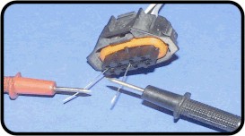
Figure 10- Using wires to probe the sensor connector block
The resistance should be a few ohms - between 1 and 20 ohms depending on model. Normal failure mode is a burnt-out heater leading to a very high or open-circuit reading (ie there is no connection at all), this would normally be accompanied by an ECU fault code, and replacement of the sensor is necessary. The heater cannot be dismantled and repaired. Here is an attempt to show typical readings for some vehicles, but bear in mind this is very approximate and the precise value is unimporant - we are mostly looking for an absence of any value.
| Vehicle Type | Expected Approx Resistance (Ohms) |
|---|---|
| Most Vehicles 1990's -> 2000, remotely sited cat, sensor on downpipe or right underneath | 5.5 - 8.0 depending on sensor make |
| Most Vehicles 2000's onwards, 4-wire sensors only, with close coupled cat | 14 - 16 |
| BMW with Bosch ECU, 1990's -> 2000's | 2.0 |
| NGK-sensor-equipped Hondas | 12 - 14 |
| Denso-equipped Toyota, Honda, Jaguar | 1.0 |
Depending on your meter you may have to minus the value of the resistance of the test leads themselves - touch the two probes directly together to get this value, normally less than 0.4 Ohms.
Modern ECU's can be very fussy about heater ratings - if it is out of spec it will trigger a fault code and LOS mode. This precludes the fitment of most universal sensors unless we recommend it as being suitable; all our sensors are tailored for the specific application they are needed for and you should contact if in doubt.
The difference in heater ratings is determined by a number of factors including
- the sensor's location in the exhaust stream - the closer it is to the engine then the less power the heater will have to supply to keep the sensor at its operating temperature
- The performance rating of the engine
- The internal arrangement of the sensor - for example internal baffling attempts to keep the sensor up to temperature when used remotely further down the exhaust pipe
- A too-high rating would cause the element to burn out prematurely
- Lean-burn strategy engines need a precisely calibrated sensor with a fast-response heater to improve the controllability of the engines fuelling and thus improve fuel economy
Note that the heater elements are self-regulating by nature so should stabilise themselves once up to temperature. This is why no independent heater control feedback loop is used. Remember that the more higher powered the heater, the lower the resistance measured will be.
Using a lambda tester
Specialist lambda sensor testers are available to test the output. They consist of a row of eight or ten LEDs which will light up progressively according to the sensor voltage output. The same effect can be achieved using a portable oscilloscope as detailed above, or as a last resort a digital multimeter.
If you must use a multimeter, ideally you should obtain one that can store max, min and mean (average) readings. A cheap multimeter can be used with success if the display refresh is reasonably fast so if you have a normal meter lying around, feel free to give it a try.
However, the one thing you must NEVER do is try to use an analogue multimeter (the type with a swinging needle). All multimeters have a property known as "input impedance" and this is just too low with an analogue meter. This will allow excessive current flow through the wires you are testing and may break apart the layers that make up the sensing element, or perhaps even blow some holes in it!
Before you start, you will need long flexible wire probes capable of being 'trapped' in the lambda sensor's connector, or you will need some insulation displacement connectors that can forcibly poke through the insulation to get at the signal wires. You may be able to find crocodile clips with a piercing spike that can achieve this, but what we don't recommend is stripping back a piece of the wire's insulation. However, if you were to do this, make sure it is well insulated with several layers of PVC insulating tape afterwards.
Find an assistant to hold the throttle when you instruct. Choose the grey and black wires, or on a Titania sensor, choose the yellow and black wires (refer to the section below on wiring colours). Start the engine and let it warm up. Reset the average readings in your meter. Hold the revs at 2000-2500 RPM for thirty seconds, then let go of the throttle. Press ('blip') the throttle once more briefly then hold your meter's readings. If you are using the oscilloscope method, find the max, min, and average readings from the waveform as you conduct the test. The LED lambda tester is calibrated to preset voltage values on each led, so it will be easy to read the voltage output. Use the following table to help diagnose if the sensor is faulty.
 |
Figure 11 - Interpreting voltage readings after Lambda testing |
|
Testing lambda output for rich/lean conditions
There are two methods of doing this. Firstly, by in-car diagnosis. For OBDII equipped vehicles readings can conveniently be taken using a hand-held tester. For earlier vehicles or where a tester is not available, or where you want to measure the voltages directly you will have to get a bit creative, but this method will allow real driving conditions whilst looking at the sensor output.
Firstly, connect up your scope/multimeter/lambda tester as detailed in section 11. The wires need to be brought into the interior of the car where the passenger sits. You will probably have to extend the wires to make them reach. Any lengths of flexible cable will do, perhaps a multi-core type. An assistant will be required to drive the car.
Be careful routing the wires out of the engine bay. You may use a spare grommet where the alarm wires come through. We have also heard of people routing the wires past the bonnet and then in through the passenger door or window. Be careful to use nylon cable-ties regularly along the wire's length to secure your wires to mounting points (the car's existing wiring harness is very suitable), and obviously keep wires away from hot objects.
Find somewhere quiet and safe and drive the car at a steady speed. The sensor is in closed-loop mode and should look like Figure 12. Note down the voltage readings at each extreme, and the average voltage.
Figure 12 - Lambda output graph with ECU running in closed-loop mode. Notice how there are 8 central cross-overs during this 10 second period, and the centre point of the graph is at 450mV. Note this graph is heavily filtered for clarity - you graph will include high frequency noise too but the basic shape should be the same.
Instruct the driver to check for other traffic, and if it is safe to do so, accelerate hard. The graph should initially look like Figure 13, then level off to the upper voltage for as long as you are accelerating. Try to note this upper voltage value.
Now instruct the driver to lift off the throttle and let the car gradually slow down. The engine should be running ultra lean and the graph will initially look like Figure 14 then settle down to a lower voltage reading. Record this lower value. Finally try to hold (freeze) the display when back in closed loop mode (ie. at constant speed) to check the frequency of the graph. If you imagine a central line on the graph at 450mV, there should be between 7 and 8 crossovers of the central 450mV point in 10 seconds.
Figure 13 (left) - Lambda output graph in Rich condition (accelerate). The graph will settle on the upper level. Notice how it is at 0.8 volts when rich.
Figure 14 (right) - Lambda output graph in Lean condition (over-run). Notice how the graph falls to below 0.2 volts. All these graphs show a sensor and ECU system that is probably okay.
The other method involves artificially influencing the mixture strength with the car at rest. We can then see the operation of the lambda sensor.
Firstly, you will need to find a way of letting lots of extra air into the intake whilst the engine is running. There are two easy methods -
- Removing the brake servo hose, but make sure you loosen the clips first, obtain replacement worm-drive hose clips ('Jubilee clips'), and don't force the pipes off the plastic elbows to the extent that they become broken.
- Simply removing the oil filler cap will let extra air in via the breather system, but may not be as effective
Then you will need to find a way of making the mixture rich. You can do this by two methods
- Partially restricting the airflow at the intake to the air-box. This may require a small amount of trunking to be removed first. Don't let anything get sucked into the air intake, and ONLY block the entrance at idle speed. An air intake is a dangerously powerful air pump at speed!
- Using an UNLIT propane blowtorch to blast into the air intake. This will have the effect of increasing the mixture strength as there will be less oxygen available for combustion. Do NOT light the blowtorch!
The point of doing this test is to figure out how fast the sensor reacts to change. One of the failure modes of a lambda sensor is sluggish operation. Keep watching the graph as you conduct the tests.
Firstly, force the engine to go lean. Remove the pipe or filler cap, whichever method you chose. The voltage should change in an instant. It should fall to zero, then start working its way back up (slowly). This is due to the ECU recognising the lean signal and increasing the injector pulse to try and richen it up again. Block the hose or replace the cap quickly. The reading should instantly rise to about 900 mV, then start to fall again, before finally going back to cycling up and down.
Now, we can force the engine to go rich. Blow the UNLIT propane blowtorch into the air intake, or block it partially, whichever method you prefer. The voltage should rise to about 900 mV, then start falling off as the ECU compensates by reducing the injector pulse width.
Faulty sensors can hover around one intermediate voltage and not cycle up and down. A sensor producing no voltage under any circumstances is definitely in need of replacement.
Please note: the procedures outlined in this section are reasonably advanced and require a degree of skill and knowledge of your vehicle. Also, since these procedures were written a few years ago, it has become common for a DIY motorist to have both an OBD-II equipped car and a suitable scan tool to read values via a computer in real-time. If you are a regular DIY mechanic, working on an older vehicle, and simply want to try them out, these tests should cause no problem enabling you to physically test the operation of the system. But please, if you are a little unsure about anything, and can't find any help, then don't do it!
Why use an original sensor from Lambdapower, and not a universal type?
There are many reasons not to use a universal type sensor.
- Our sensors are specifically tailored for each application. A universal sensor cannot be. Manufacturers demand differences most importantly in protection can design and heater rating, depending on whether the sensor is close-coupled or not. Also differences exists in internal grounding arrangements in the sensor itself, harness and connectors, and also grommets where required
- The specification of the materials used meet and exceed the standards of the vehicle manufacturers - this includes the sensor body, the plastics used in the connector block, and even the connector pins themselves
- A lambda oxygen sensor is a difficult and time-consuming item to manufacture. The total time from start to finish is two weeks. This is because of a complex precision process in forming the sensing element and coating it with the correct precious metals in precise quantities.
Cheap universal sensors leave out some of these fine finishing processes in order to reduce the amount of time to manufacture, and thus reduce costs. The result is a sensor that may work for a short time, but cause more problems within six months time. The only way to be sure you will have no problems in the future is to fit an OE spec sensor from Lambdapower. Buying a cheap sensor is ultimately a false economy.
- All aspects of the sensor's function will be correct, including insertion depth and protection tube design as detailed above, and heater wattage rating
- A big problem plaguing universal sensors is water ingress into the spliced connections. This leads to corrosion, and a high resistance across the join. This upsets the signal sent back to the ECU, thus defeating the object of fitting a new sensor in the first place.
- The possibility of corroded connectors is reduced as the multiplug wiring is new.
- A considerable amount of time and effort is saved on fitting
Due to considerable demand, we now offer a universal sensor as an option whenever possible. However we have a large number of different types to choose from according to the vehicle type. Our most popular universal type sensors can be seen on this page.
Look at this example sensor - in this case for a Volvo V40 2.0T. It is a Titania sensor. Click to enlarge the image.

Notice that the specification of the sensor complies exactly with the original - the securing pegs and the extra rubber sleeving for abrasion protection are both present, as well as the sensor itself being the correct type for the 2.0T engine (B4204T). Below is a close-up of the connector itself, again being exactly the correct specification for the vehicle.
Our sensors are only top-quality OE spec items made by original equipment manufacturers. The advantages of only supplying top-quality sensors are clear:
- Every sensor has been certified by the German Technical Inpectorate (TUV) for compatibility with the original equipment type.
- They comply 100% with the vehicle manufacturer's specifications
- Each sensor is tested before delivery
- High service life, unlike low-cost universal copies that will fail within a few months
- Serves to optimise fuel consumption, engine output, driving properties, and ensure emissions are low.
- Up to 15% fuel saving in comparison to a significantly aged or faulty Lambda sensor
- Prevents the possibility of damage to the catalytic convertor or MOT emissions failure on lambda control loop.
- The cost of replacement of an aged lambda with a quality new unit will be recouped within 3-6 months due to savings in fuel costs - any further savings beyond that time are then all yours.
If you are still looking for a cost-effective but lower cost Universal lambda sensor, please contact us using your vehicle details. There is a link on this page listing our most popular Universals.
What is a universal sensor?
The word "universal" is a misnomer - there is no such thing as a truly universal sensor that will fit any vehicle. All lambda sensors need to be tailored to fit the car, even when they come as a universal fitment.
Lambdapower now supplies universal type sensors. We have a choice of about twelve "universal" lambdas to choose from. The type that makes a closest match to the specifications of the original part will be supplied. If no close match is available, then the only option is using an OE type. Lambdapower's technical spec sheets and years of experience tell us which sensors will work in which vehicles. Feel free to ask us to find you the correct sensor for your car.
A plain lambda sensor advertised as "universal" cannot possibly cover all potential vehicles it might be fitted into, you need advice first as to which sensor is suitable for your vehicle. Obtaining an OE spec sensor removes the guesswork, but there may be certain circumstances where a universal type is acceptable, for example where the resale value of the car does not justify fitting a particularly expensive OE sensor.
Universals can be unsuitable for the following reasons
- Most manufacturers use different types of multi-plug. This means that the user of a universal type sensor has to cut the old sensor plug off and attach it to the new sensor's wires. Our cheapest sensor is a branded manufacturer supplied with crimp type butt splice connectors but must be adequately waterproofed after installation. The Bosch system we also sell has a waterproofed terminal block which is meant to protect against water ingress
- Even experienced motorists, which includes us, may have difficulty attaching new sensors to wires on old vehicles, the copper in the wiring harness to the sensor will have oxidised inside its PVC covering and will no longer be suitable for crimping a connection to. This is the cause of the characteristic green powder surrounding old connections and blackened copper exposed when the insulation is stripped back.
- Soldering is at best 'difficult' to a corroded wire such as this, and attempts to remove the oxidation will often lead to the wire breaking internally, as the copper tends to become brittle with age due to manufacturing impurities.
- Bargain basement budget sensors from non-recognised manufacturers, the most substantial differences are those you cannot see - lambda manufacture is a time-consuming process, taking a full two weeks from start to finish for each sensor. In order to cut costs, manufacturers of cheap sensors leave out some of the manufacturing stages in order to cut production time down to about a week. Such stages would include the fine polishing and grinding processes of the ceramic element (in order to ensure optimal accuracy) and some of the chemical additives designed to prolong the life of the sensor. All this cost-cutting affects the quality of the sensors output, and also dramatically shortens it's life. Buying a cheap sensor is a false economy, this is in common with other engine management components - we know of imitation Bosch parts such as airflow meters selling for a quarter of the price of the original item, but only lasting six months or so before needing replacement again.
- A cheap sensor selling for a fraction of the price of OE spec parts from a recognised manufacturer will be perhaps 15+ years out of date as far as sensor technology is concerned - there was a time when the first automotive lambdas would require replacement every few thousand miles, this is not so anymore due to advances in manufacturing technology.
- Differences are also apparent in the sensor head, its protrusion into the exhaust gas stream, and its protective cover, each tailored once again to individual applications. The metal protection can has dozens of different configurations according to specific application. We have also had instances where incorrect universal type sensors have been fitted to incompatible vehicles, thus meaning that even after the new sensor is fitted, the ECU will still ignore its output ass unsuitable and adopt LOS ('limp-home') mode regardless.
- OBD-II vehicles (2000 on) may also register fault codes if sensor specifications are not to OE standards. For example, codes can be logged for heater resistance out of spec which it may well be on a non-OE sensor. Additionally, the manufacturer may make additional demands on the specification of any sensor, including internal details.
- Heater powers are rated differently according to the sensor's location and the manufacturer may require additional design safeguards to prevent against water splash, again influenced by the location of the sensor. This will affect the vent location and type.
So the solution is to either fit a direct-fit part, or contact us first so we can assist you selecting a suitable universal sensor for your car. For some vehicles there are no universals that will do the trick, and only someone with specialist knowledge will know from experience.
But what if i want to use a universal sensor?
We now sell a range of 'universal' lambda sensors. These can be used in certain circumstances for example where the resale value of the car does not justify fitting a particularly expensive OE sensor.
However, it is important to realise the same rules still apply with regards to quality of sensor. A cheap sensor of unknown origin will fail after a few months, perhaps not be compatible with the car in the first place, and often force you to incur extra expense by replacing the sensor prematurely, either because of premature failure, or because bad advice lead you to buy a sensor not suited to your vehicle.
The word "universal" is a misnomer - there is no such thing as a truly universal sensor that will fit any vehicle. All lambda sensors are tailored to fit the car, even when they come as a universal fitment.
At lambdapower we have a choice of about twelve "universal" lambdas to choose from. The type that makes a closest match to the specifications of the original part will be supplied. If no close match is available, then the only option is using an OE type. Lambdapower's technical spec sheets and years of experience tell us which sensors will work in which vehicles.
Please see this page, it contains details of some of our Universal sensors, and please ask us via email to check which one is suitable for your car
Can I clean my old lambda sensor?
It is sometimes possible to clean contamination off a suspect sensor, but only in the sense of 'cleaning' in situ. It is not possible to remove it and 'wash' it clean like you would a dirty spark plug. You would suspect contamination of the sensor if you have carried out some of the other checks detailed here and the sensor response seems to be sluggish or centre around the wrong voltage level.
Run the engine at no load for 3000rpm for a few minutes. Don't blip the throttle or let the engine race above 3000rpm. Revving an engine hard with no load is not good for it.
The sensor will now be nice and hot and it should be able to produce a voltage if it is good. You may wish to repeat your voltage checks at this point. If you are lucky, you will have burned off whatever deposits were preventing the sensor from working properly.
However, should the symptoms return again you may suspect two things:
- The heater of the sensor is non-functioning - test it with reference to the instructions above
- The sensor is indeed contaminated or has some other internal malfunction and needs replacing after all.
It is worth remembering that if the sensor gets too hot any contaminants may fuse together and form a coating that will never be removed. This situation may arise if the ECU is running too rich due to the sluggishness of a failing sensor.
Why do the sensors have different numbers of wires?
The sensor on your vehicle will have different numbers of wires according to which type of sensor it is.
Single wire sensors are the earliest and most basic type of sensor with only a single signal wire. The sensor gets its operating heat from the exhaust gases themselves, and has a return ground (or if you prefer - earth, negative, 0v) path through the exhaust and manifold to the engine. Two wire sensors have an extra ground path down one of the wires. There can be a surprising amount of voltage difference between earth points on a car, and supplying 0v through a separate wire reduces the amount of noise in the signal, caused by for example rusty manifold bolts or poor engine earth connections.
Three wire sensors have a signal wire and two heater wires. This brings the sensor up to operating temperature quickly and keeps it there even when the exhaust is running cool, for example during idling. Four wire sensors have an additional ground as described for the two wire, and also a heater (two wires).
Signal wires are black, the added earth will be grey, and the two heater wires are normally white. The heater wires are not fussy about polarity, which explains their identical colour.
A Five wire sensor is identified as a wideband sensor, and normally the harness plug has one or two spare pins (seven pins in total). The extra wires of the wideband sensor are used to supply a bias voltage to a chemical device known as an 'oxygen pump', which modifies the behaviour of the Zirconia element and provides a much more accurate measure of exhaust gas O2 content.
Can I test my wideband (also known as planar, or 5-wire) sensor?
The operation of the planar or wideband sensor is substantially different to traditional types. There is no meaningful DIY method of testing this sensor, apart from using an OBD-II scan tool. However, if your car has logged a sensor heater circuit fault, you can test the heater resistance with a multimeter, across the WHITE and GREY wires. Reading should be about 4.5 ohms.
The best way to test operation is to use a scan tool plugged into the OBD-II (on board diagnostics) port of the vehicle. This will translate the output of the sensor into a form you will be able to read.
Because of the internal circuitry used in a wideband oxygen sensor, you can't hook up a voltmeter or oscilloscope to read the sensor's output directly. A wideband O2 sensor produces a signal that varies not only in amplitude but direction. That makes it quite different from a conventional oxygen sensor that produces a voltage signal that bounces back and forth between 0.1 and 0.9 volts.
Most wideband sensor failures are accompanied by a fault code from the engine ECU, although we have seen instances where this is not the case. The ECU will log an oxygen sensor code if the sensor reads out of its normal range, if the readings don't make sense to the ECU (eg. failure to indicate lean when lean conditions exist) or if the heater circuit fails.
You can use the scan tool to read the actual air/fuel ratio, and to check the sensor's response to changes that should cause a change in the air/fuel ratio. The procedures are not the same as for traditional narrowband sensors though. For example, in a narrowband system, suddenly snapping the throttle wide open causes a sudden and brief lean condition followed by a richer mixture as the ECU compensates. But in a wideband system, this situation doesn't arise anymore due to new mixture control strategies that are made possible with the more accurate planar O2 sensors. The air/fuel ratio will remain steady when the throttle is snapped open.
One thing to keep in mind about wideband O2 sensors is that they can be fooled in the same way as a conventional oxygen sensor by air leaks between the exhaust manifold and head, and by misfires that allow unburned oxygen to pass through into the exhaust. Either will cause the sensor to indicate a false lean condition which, in turn, will cause the computer to make the engine run poorly, idle badly, or fuel constantly rich.
How can the sensor element become contaminated, are there any physical signs, and which chemicals cause this?
The biggest enemies of the sensor element, narrowband or wideband, are as follows.
Silicon - blowing a head gasket can allow silicon to enter the exhaust and contaminate the sensor. Some fuels are also prone to high levels of SiO2 (Silicon Dioxide) in them and this will poison your catalytic convertor too. We recommend only filling your car up at branded filling stations (eg. BP, Shell), and not at supermarket filling stations, which source petrol from less advanced refineries. Other contaminants exist in cheaper fuels, and you are doing many parts of your engine a favour by not using them.
Silicon contamination shows up as a white coating on the sensor tip.
You should avoid lubricating any part of the inlet tract with a silicone based lubricant. The manufacturers of WD-40 say there is no silicone in their product. This may also be true for other similar products. If any linkage mechanisms need cleaning up, use a toluene or ethanol-based carburettor cleaner, then lubricate using a normal oil-can or a good quality grease.
Oil burning can allow phosphorus to enter the exhaust and contaminate the sensor. Realise that oil contains many impurities once it has been used in your engine for a while - combustion by-products and minute particles of metal worn away from contact surfaces both reduce the lubricating properties of the oil over time.
Oil burning can be caused by smoky turbochargers, worn bores, or leaky top-ends (valve stem oil seals, valve guides). Regular oil changes with an appropriate oil for your vehicle will prevent this. If your engine is running rich it will result in a phenomenon known as 'bore wash', where excess fuel will remove the micro-thin coating of oil on the cylinder wall thus leading to accelerated bore wear.
Misfiring will fool the ECU into thinking the mixture is lean due to the presence of excess oxygen in the exhaust gases. This will cause it to enrichen the mixture when it is not needed, leading to increased fuel consumption.
Metallic contaminants - failure to change the oil regularly will cause this; dirty oil is full of metals worn away from the internals of the engine during its normal course of running. As all engines burn a tiny amount of oil, these metals will end up in the exhaust gas stream and will gradually poison the platinum coating on the sensor element.
Carbon fouling shows up as black powder on the sensor tip. It is a good idea to take any vehicle used only around town for an occasional motorway cruise to loosen sooty deposits within the engine.
Home or professional auto repairs that have used silicone gasket sealer that is not specifically labeled "Oxygen sensor safe", if used in an area that is connected to the crankcase, will damage the sensor. Such areas include valve covers, oil pan, or nearly any other gasket or seal that controls engine oil.
If a car is running rich over a long period, the sensor may become plugged up or even destroyed. Undercoating, antifreeze or oil on the outside surface of the sensor can kill it. This is because a reference gas has to be taken from the atmosphere and should not be contaminated. It is possible for a sensor to fail on either the exhaust or the atmosphere side of the sensing element.
What are the wiring colours on the harness?
Here are popular wiring colours for Lambda harnesses. You will need this information if fitting a universal type sensor. Please note a couple of things about wiring colours, firstly they often seem counter-intuitive, for example one would normally expect BLACK to be earth, but it is the signal wire, or alternatively one of the heater wires.
Also, these wiring colours are on the Lambda Sensor's side of the harness. When these wires connect with the vehicle, the colours on the vehicle side will usually be completely different.
Zirconia sensors
For NGK, Bosch, and the majority of Zirconia sensors with 1, 2, or 3 wires| Zirconia 1-wire: | BLACK = signal |
| Zirconia 2-wire: | BLACK = signal GREY = ground |
| Zirconia 3-wire: | BLACK = signal WHITE = heater WHITE = heater |
This table will help you fit a universal sensor. For four-wire sensors and three-wire Subaru (import), read across the rows:
| Heater | Heater | Signal | Ground | |
|---|---|---|---|---|
| Type A: | White | White | Black | Grey |
| Type B: | Black | Black | Blue | White |
| Type C: | Purple | White | Black | Grey |
| Honda: | Black | Black | Blue | White |
| Honda 2: | Black | Black | White | Green |
| GM: | Brown | Brown | Purple | Tan |
| Subaru: | Red | Black | White+Brown | (none) |
| LP Uni Special edition: | Orange | Orange | Black | Grey |
For Five-wire Wideband sensors:
| Pump | Sense | Heater | Heater | Ground | |
|---|---|---|---|---|---|
| Type A: | Red | Yellow | White | Grey | Black |
| Type B: | Red | Blue | Yellow | Yellow | Black |
Titanium sensors
For Titania sensors| Titania type 1 | RED = heater +ve WHITE = heater -ve YELLOW = signal +ve BLACK = signal -ve |
| Titania type 2 | GREY = heater +ve WHITE = heater -ve YELLOW = signal +ve BLACK = signal -ve |
| Titania type 3 | BLACK = signal GREY = ground WHITE = heater WHITE = heater |
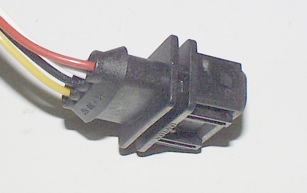
Why are there so many different types of connector? Aren't all sensors the same?
No. All sensors are not the same, and there is no "universal" fitment for lambda sensors, much in the same way as you wouldn't expect body panels or gearboxes from different manufacturer's cars to fit your own. The sections above on universal lambda sensors explain the differences. If you need a universal sensor, contact us, we can guide you to the correct one.
Manufacturers may change the type of connector used for a few reasons.
- Different versions or updates of the fuel injection system may use a different type of sensor. Changing the fitment avoids confusion on replacing the part
- To allow easy distinction between front and rear sensors on OBD-II cars. Often one will be a Wideband sensor, and the post-cat sensor will be a 4 wire Zirconia type.
- To allow distinction between the lambdas on corresponding cylinder banks on multi-lambda setups. Such as used on Avensis, N19 engined BMW's
- Because the engine management system has been changed and the manufacturer of the fuel injection specifies a different type of connector, or perhaps a sensor with a different number of wires.
- To discourage obtaining parts for another manufacturer's vehicle and attempting to fit them. This could upset the ECU with an incorrectly specified part. This is also a reason not to use a universal sensor.